Following information is valid for DC-motors (series GR/G and BG):
Performance figures given in the tables are measured in accordance with EN60034. These figures are based on the assumption that the motor is freestanding and that certain other theoretical conditions are fulfilled. In a real application, the rated torque of a motor will often be considerably higher. For this reason, the data tables in the product PDFs quote the rated torque measured according to EN (lower value) and also the torque with the motor mounted on a thermally conducting steel plate with the dimensions 105 x 105 x 10 mm (value in brackets). For many applications, it is sufficiently accurate to take the most important data from the motor characteristic diagrams and data tables. Although tolerances and temperature influences are not taken into account, the data is accurate enough for approximate calculations. The degree of protection quoted relates only to the housing ? adequate sealing of the shaft is the responsibility of the customer
The dc motors can be combined with control electronics, gearboxes, brakes and encoders in a modular system to provide a flexible, adaptable, market-oriented solution.
Nominal voltage UN (VDC)
The DC voltage that is applied to the commutation electronics as a system supply voltage. All rated data in our catalogs are with reference to this voltage. Motor applications are, however, not restricted to this voltage.
Rated torque MN (Ncm)
The torque that can be produced by the motor, operating continuously in an ambient temperature of 20?C.
Rated speed nN (rpm)
The speed of the motor when it is operating at rated torque (6).
Rated current IN (A)
The current drawn from a DC source when the motor is operating at rated torque (7).
Starting current IA (A)
The current required to produce the starting torque. For motors with electronics, the starting current may be higher than the permissible peak current (4).
Starting torque MA (Ncm)
The maximum torque the motor can produce (2).
Rated power PN (W)
The output power which the motor can produce continuously; it is calculated from rated speed and rated torque.
Moment of inertia of rotor JR (gcm2)
The moment of inertia of the rotor is the factor that determines the dynamic properties of a motor.
Peak current Imax (A)
The maximum current for electronics or motors with integral electronics (5).
Max. permissible voltage range Umax (VDC)
The minimum and maximum permissible input voltage for electronics or motors with integral electronics.
Recommended speed control range nmax (rpm)
The regulated speed range within which rotor position sensing by hall sensors ensures a smooth torque curve. As a rule, this range can be extended by installing a rotary encoder. The data in this catalog contain product specifications, but are not a guarantee of particular properties. The stated values are subject to tolerances. Any supplementary information and safety instructions given in the operating manual must be observed with no exceptions. We reserve the right to make technical changes and to restrict availability.
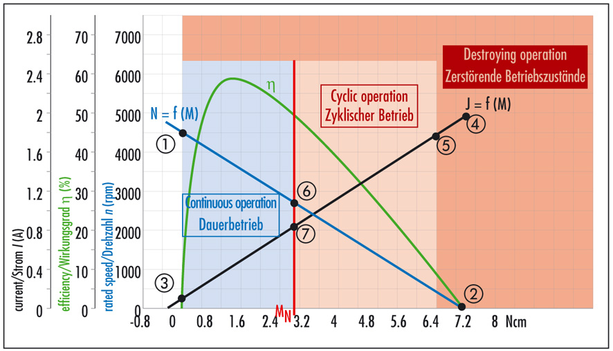
MOTOR CHARACTERISTIC DIAGRAMS
Speed curve (blue)
This curve shows the speed characteristic at constant voltage. Its end points are the no-load speed n0 (1) and the theoretical starting torque MA (2).
Current curve (black)
The current curve shows the relationship between current and torque. Its end points are the no-load current I0 (3) and the starting current IA (4).
Efficiency curve (green)
The efficiency is the relationship between the mechanical power output and the electrical power input. The curve shows the efficiency with the motor in cold condition; as the motor warms up, the curve shifts accordingly.
Rated torque MN/ Starting torque Mmax
The rated torque (red) is the limit of the continuous operation region (shaded blue). In the region between the rated torque and the maximum permissible torque, the motor must only be used intermittently (shaded orange). Operating conditions above the maximum permissible torque result in demagnetization of the permanent magnets (shaded red).